


The probability (likelihood) that a component or system will perform its intended function with no failures for a given period of time (mission time) when used under specific operating conditions (test environment or operating environment).
Click the following titles to switch RMA Application Topics: Synopsis, Maintainability (M), and Availability (A)
or submit feedback, improvements or corrections via theR&M Feedback Form to enable the continued readiness
and continuous relevance of the data provided within this site.
- Reliability Prediction
- Reliability Allocations
- Reliability Block Diagrams
- FMECA
- Worst Case Analysis
- PSA/EPSA
- Fault Tree
- PRA
- Sneak Circuit
- Single Event Effects Analysis
- Software Assessment
Reliability Prediction
The primary purpose of a reliability prediction is to provide guidance relative to the expected reliability for a product as compared to the customer's need, expressed or implied, for the product. The use of a prediction is a means of developing information for design analysis without actually testing and measuring the product capabilities.
Reliability prediction plays a major role in many reliability programs. Standards based reliability prediction relies on defining failure rates for the components of a system based on statistics or modeling (e.g., Physics of Failure Handbook or Physics of Failure Practitioner's section), depending on the types of components, the use environment, the way the components are connected and the reliability prediction standard. These component failure rates are then used to obtain an overall system failure rate.
Early predictions are strongly encouraged in the product Concept/Planning phase to support design trades or other analyses as necessary. This is when most decisions are made regarding redundancy, parts, materials, and processes. The first analysis should be considered as soon as the concepts are ready to be traded or initial design data is available. Predictions should be continued throughout the design process, being updated as more detailed design information becomes available. The later predictions evaluate stress conditions and life limiting constraints, as well as the relative impacts of implementation issues. After launch predictions should be updated with system performance/use data to support mission extension and disposal decision making, since pre-launch usage assumptions may no longer be valid.
When Performed
As soon as a concepts are formulated or system block diagrams are available and updated throughout system design and operations.
Value
Predictions provide an array of benefits to a product development, including:
- Determining the feasibility of a proposed product's design meeting mission goals
- Comparison of product design concepts to meet mission goals/objectives
- A means of ranking or identifying potential reliability design problem areas
- Evaluation of alternate design, redundancy, parts, materials, and processes
- A quantitative basis for design trade studies that could be informed by testing or modeling
- Redundancy is optimized but not excessive
For Performance see R&M Guidance and Reference Data: Methods page
Reliability Allocations
Reliability allocation involves setting reliability objectives/goals for a Program based on the Program objectives and mission profile. Once the Reliability Program goal/objective has been determined the Reliability allocation to each Mission and System can be determined. This should occur in the initial development stages of design prior to designing major system upgrades. This can also be allocated to Element and subsystems if desired and based on the Procurement and Design strategy. The simplest method for allocating reliability is to distribute the reliability objective uniformly among all the subsystems or components. While uniform allocation is easy to calculate, it is generally not the best way to allocate a reliability objective. The "best" allocation of reliability would take into account the cost or relative difficulty of improving the reliability of different subsystems or components.
When Performed
Early in design and to support FMECA and FTA quantification
Reliability allocation is the top-down process of subdividing a system reliability requirement into subsystem and component requirements.Once the allocation goal/objective has been identified, an analysis starts from past experience (and other data sources and techniques) and performed at a higher level of subsystems instead of lower levels such as components sourced from different vendors. This level of detail is more appropriate during the first stages of design and allows for identification of areas that currently do not meet there design allocation. It is not efficient to develop a detailed design and then have to redesign and reallocate reliability if the initial allocation is not achievable. The assignment of reliability values between the components can be made based on the complexity, criticality, estimated achievable reliability, or whichever factor the engineering team performing the analysis deems important.
Identifies potential single point failures requiring corrective action. Identifies critical items and assesses system redundancy and mission risks due to failure. Serves as a failure/anomaly triage tool.
Early identification, tracking, and control of critical items through the preparation, implementation, and maintenance of CILs will provide valuable inputs to a design, development, and production program. From the CIL activity, critical design features, tests, inspection points, and procedures can be identified and implemented that will minimize the probability of failure of a mission or loss of life.
Value
Translation of product reliability goals into reliability goals for the components making up the product.
To aid in identifying reliability drivers for a given design or evaluating the reliability of competing designs, e.g. trade studies.
For Performance see R&M Guidance and Reference Data: Methods page
Reliability Block (Logic) Diagrams
RBDs permit the entire team to consider tradeoffs and impact of decisions on system reliability and balance priorities across various elements of a system.
Not every element of a system has to achieve high-reliability performance when not effectively making any different to the overall system reliability. Focus improvement activities on the elements that actually impact the system’s ability to achieve the goal.
RBDs provide a vehicle for tradeoff analysis and decision making. Given constraints of weight and reliability, and a set of options to improve a power supply reliability. The best option may involve doubling the weight by using redundant power supplies, yet a less reliable option may only use a different circuit design and components. This becomes interesting when the lower weight solution does not meet the power supply reliability allocated goal.
When Performed
Used early in a design cycle, it allocates reliability among blocks, guiding architecture and design decisions to achieve an overall system reliability requirement.
Used on established designs, it sorts every component into blocks according to their function to expose the distribution of failure rates.
Value
RBDs and their resultant reliability estimations provide an array of benefits to a product development, including:
- Determining the feasibility of a proposed product's design meeting mission goals
- Comparison of product design concepts to meet mission goals/objectives
- A means of ranking or identifying potential reliability design problem areas
- Evaluation of alternate design, redundancy, parts, materials, and processes
- A quantitative basis for design trade studies that could be informed by testing or modeling
- Redundancy is optimized but not excessive
For Performance see R&M Guidance and Reference Data: Methods page
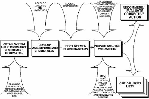
Failure Mode and Effects Analysis / Critical Items List (FMEA/CIL)
The Failure Mode and Effects Analysis (FMEA) is performed to identify failure modes. As part of this process, critical failure modes that could lead to loss of life or loss of mission are also identified. These critical failure modes are then placed into a Critical Items List (CIL), which is carefully examined for programmatic control by implementing inspection requirements, test requirements and/or special design features or changes which would minimize the failure mode occurrence.
Failure Mode and Effects Analyses and resulting CILs can be used not only as a check of the design of systems for reliability, but also as main design drivers for the product or service. Reliability management is the activity involved in coordinating the reliability analyses of design, development, manufacturing, testing, and operations to obtain the proper performance of a given product under specified environmental conditions. Reliability management interfaces with the program management function, the design function, the manufacturing function, the test and inspection function, and the quality function.
Reliability management is approached through the formulation and preparation of reliability plans, the performance of specific product design analysis, the support of classical reliability analysis activities, and project/product team participation using concurrent engineering methodologies (see NASA Reliability Design Practice GD-ED-2204).
Failure Mode and Effects Analysis Criticality Analysis (FMECA)
Failure mode and effects analysis (FMEA) and failure modes, effects, and criticality analysis (FMECA) are methods used to identify ways a product or process can fail. The basic methodology is the same in both cases, but there are important differences between the processes.
Qualitative versus Quantitative: FMEA provides only qualitative information, whereas FMECA also provides limited quantitative information or information capable of being measured. FMEA is widely used in industry as a "what if" process. It is used by NASA as part of its flight assurance program for spacecraft. FMECA attaches a level of criticality to failure modes; it is used by the U.S. Army to assess mission critical equipment and systems.
Extension: FMECA is effectively an extension of FMEA. In order to perform FMECA, analysts must perform FMEA followed by critical analysis (CA). FMEA identifies failure modes of a product or process and their effects, while CA ranks those failure modes in order of importance, according to failure rate and severity of failure.
Critical Analysis: CA does not add information to FMEA. What it does, in fact, is limit the scope of FMECA to the failure modes identified by FMEA as requiring reliability centered maintenance (RCM).
When Performed
The FMECA is a living document during the development of a design. It should be scheduled and completed concurrently with the design, so that it can help guide design decisions. The usefulness of the FMECA as a design tool and in the decision- making process is dependent on the effectiveness and timeliness with which design problems are identified. Remedies that would be practical for design issues in a timely FMECA become extremely difficult and expensive if the analysis is performed after the equipment is built.
Value
FMEA/FMECAs and their resulting failure modes (with causes, severity, likelihood, effects, detection and mitigating assessments), critical item identification, and single point failure modes highlighting provides, product insights and risks assessments that promote improved product robustness throughout its life by identifying:
- the potential for irreversible physical and/or functional damage;
- how damage/failures propagate or not;
- how damage/failures impact the system (locally and globally);
- the means available for failure detection, isolation, and/or compensation;
- the symptoms and causes of failure for anomaly investigation;
- monitoring and redundancy strategy validity and viability;
- recovery strategies (determination and optimization of contingency operations and autonomous recovery/safing plans) prior to failures;
- the risk/effectiveness of corrective action implementation plans; and
- the risks to mission success and safety architectures.
For Performance see R&M Guidance and Reference Data: Methods page
Worst-Case Analysis (WCA)
WCA is a design analysis used to verify compliance with performance requirements for flight equipment and to help prevent design flaws. WCA determines the performance margins in order to demonstrate proper functionality of the system throughout the mission life under combinations of adverse conditions. The analytical results with positive design margin will ensure proper operation of the equipment under the most unfavorable combination of realizable conditions. In the opposite case, negative margin will identify potential problems for very specific performance requirements. This technique helps to design in graceful degradation at the performance margin (avoiding catastrophic failure at the boundaries). In real applications, conditions rarely stack up in the worst possible combinations, and the equipment often functions beyond the nominal mission. Because of this, the WCA is an important part of the design and development of spacecraft and instruments. Although this handbook focuses on WCA of electrical circuits, the WCA techniques are applicable to designs at all levels, including component (such as hybrids, multichip modules [MCMs], etc.), circuit, assembly, subsystem, and system. Formal WCA usually is required of all electronic equipment and performed on critical circuits, at a minimum. The WCA is an often used, valuable design practice for other engineering disciplines/systems as well (hydraulic, mechanical, etc.), but it is not always a formal deliverable for those areas.
For electronic circuits, WCA is an extension of classical circuit analysis. In aerospace applications, it is intended to estimate the maximum range of performance of the equipment due to the effects of aging, radiation, temperatures, initial tolerances and any other factors that influence performance. The approach includes variations from both electronic parts and circuit interface conditions. The circuit analysis is performed and repeated for the worst combination of extreme values of part parameters and interface conditions to determine the minimum and maximum performance. To ensure reliable performance of spacecraft circuits, it is essential that variations in these parameters and conditions be addressed as the design is developed.
When Performed
Early in the design cycle and is updated iteratively throughout the design cycle and reviews. Since WCA will help identify design and reliability issues the WCAs should completed to allow for changes to be implemented prior to testing and operations.
Value
The WCA process and results benefit design teams by:
- Validating the potential for acceptable operation throughout the entire product life cycle under the most unfavorable combination of anticipated conditions (part parameters, environmental extremes, power, inputs, loads, interference)
- Identifying and validating specified operational/input and testing limits
- Prompting design refinements to improve Reliability by managing part/circuit stresses
- Preventing design issues from being observed during test, alignment, and use, that could result in circuit damage or premature degradation.
- Validating circuits do not have Improper part applications.
For Performance see R&M Guidance and Reference Data: Methods page
Part Stress Analysis (PSA)/Electrical PSA (EPSA)
PSA/EPSA (aka Derating Analysis ) is a design analyzes the applied stresses (e.g., operating voltages, temperatures, radiation, etc.) on component/circuits to assessed operational risks. PSA/EPSA determines the performance margins or exceedances to manufacturer limits in order to demonstrate proper functionality of the component/circuits throughout the mission conditions. The analytical results with positive design margin will ensure proper operation and expected reliability of component/circuits. In the opposite case, negative margin will identify potential problems for very specific conditions or intervals. This technique helps to design in circuits and circuit protections as needed. The PSA/EPSA is an often used and valuable design practice for other engineering disciplines/systems as well (electrical, systems, etc.).
The approach includes variations from both electronic parts and circuit interface conditions and derating (power rating) parameters.
When Performed
Early in the design cycle and is updated iteratively throughout the design cycle and reviews. Since PSA/EPSA will help identify design and reliability issues the PSA/EPSAs should completed to allow for changes to be implemented prior to implementation, testing, and operations.
Value
The PSA/EPSA process and results benefit design teams by:
- Validating acceptable part selection and circuit design for the operational life cycle under nominal/derated conditions;
Identifying and validating specified operational/input and testing limits
Prompting design refinements to remove failure vulnerabilities from exceeding part ratings;
Preventing design issues from being observed during test, alignment, and use, that could result in circuit damage or premature degradation.
- Validating circuits do not have Improper part applications.
For Performance see R&M Guidance and Reference Data: Methods page
Fault Tree Analysis (FTA)
A fault tree analysis is a top-down/deductive analysis that results in a graphical logic tree that shows all the pathways through which a system can end up in a foreseeable, undesirable state or event. This event can be a loss of a function. The chief focus of a fault tree is “failure” rather than “success”. Fault trees can be used at virtually any level: module, subassembly, system, or mission. The basic idea is that logic functions such as AND, OR can be used to connect events in such a way that the various pathways to the undesirable event are clearly established.
This technique helps to identify minimum paths to failure scenarios and can be preformed qualitatively or quantitatively but it can also be used to evaluate safety/hazard scenarios.
When Performed
Early in the hardware, software, and FDIR (Fault Detection Isolation And Recovery) design cycle and is updated iteratively throughout the design cycle and reviews. Since FTA will help identify design and reliability/safety issues FTAs should completed to allow for changes to be implemented prior to testing and operations.
Value
The FTA process and results benefit design teams by:
- Validating failure detection, isolation, and/or recovery provisions/designs;
Identifying the risk of physical and/or functional events (and potentially quantifying); and what the contributors are to an event/scenario;
Evaluating effectiveness and adequacy of failure mitigations/compensations (HW, SW, and redundancy);
Determining the effectiveness of corrective action implementation plans;
Identifying the predominate risk contributors (HW, SW, or failure mode) the risks to mission success and safety architectures.
For Performance see R&M Guidance and Reference Data: Methods page
Probabilistic Risk Assessment (PRA)
A PRA is a comprehensive, structured, and logical analysis methodology aimed at identifying and assessing risks in complex and time-based technological systems. It includes input from FTs/FMECAs/ predictions that models and assesses the likelihood of event sequences.
The PRA process and results defines the events required for success and quantifies the potential for success/failure potential scenario outcomes.
- defining the dependencies between events;
- how damage/failures impact the system (locally and globally); monitoring and redundancy strategy validity and viability;
- the risks to mission success and safety architectures
When Performed
Early in the hardware, software, and FDIR (Fault Detection Isolation And Recovery) design cycle and is updated iteratively throughout the design cycle and reviews. Since PRA will help identify design and reliability/safety issues PRAs should completed to assess specific operations within the operational phase (e.g., mission extension, disposal, servicing) as well.
Value
The PRA process and results benefit mission teams by:
- Identifying how damage/failures impact the system (locally and globally);
- Defining the dependencies between events;
- Assessing event strategy validity and viability;
- Forecasting risks to mission success and safety architectures.
For Performance see R&M Guidance and Reference Data: Methods page
Sneak Circuit Analysis (SCA)
Sneak Circuit Analysis is a vital part of the assurance of critical electronic and electro-mechanical system performance. Sneak conditions are defined as latent hardware, software, or integrated conditions that may cause unwanted actions or may inhibit a desired function, and are not caused by component failure.
When Performed
Early in the design cycle and is updated iteratively throughout the design cycle and reviews. Since SCAs will help identify design and reliability issues the SCAs should completed to allow for changes to be implemented prior to implementation, testing, and operations.
Value
The SCA process and results:
- Identify unpowered and powered electronics susceptibilities;
- Identify non-trivial Back EMF paths and impacts;
- Finds multiple or floating grounds for resolution;
- Assesses the potential for unexpected configuration changes;
- Assists in avoiding failures and and circuit damage in conjunction with PSA/EPSA efforts.
For Performance see R&M Guidance and Reference Data: Methods page
Single Event Effects Analysis (SEEA)
In the space environment, spacecraft designers have to be concerned with two main causes of Single Event Effects (SEEs): cosmic rays and high energy protons. For cosmic rays, SEEs are typically caused by its heavy ion component. These heavy ions cause a direct ionization SEE, i.e., if an ion particle transversing a device deposits sufficient charge an event such as a memory bit flip or transient may occur. Cosmic rays may be galactic or solar in origin. The SEEA is a design analysis to verify both hardware tolerance or susceptibility (failure modes) for:
Temporary loss of operation
Damage to one or more pieces of hardware
Corrupted memory and logic
Corrupted data
System malfunctions, unexpected interrupts
Void/corrupted displays
Undesirable S/W execution
Timing impacts
Momentary loss of communication
Total mission/catastrophic failures
and other system performance effects caused by transient radiation environments (e.g., high-energy- charged particles and radiation). The purpose is to show that inherent device immunity or circuit mitigation techniques are adequate to prevent destructive effects and that system and circuit effects of upsets (memory state change, etc.) and voltage transients produce mission-tolerable errors.
When Performed
As early in the design cycle as possible and is updated iteratively throughout the design cycle and reviews. Since SEEAs will help identify design and reliability issues the SEEAs should completed to allow for changes to be implemented prior to implementation, testing, and operations.
Value
The SEEA process and results benefits design teams by:
- Validating of acceptable operation throughout radiation exposures of the mission;
- Identifying and validating specified operational/input and testing limits/requirements;
- Prompting design refinements to improve radiation tolerance/protection by managing impacts;
- Improve system safety and fault tolerance through corrective actions.